
How to Select Mining Cable: Voltage, Size, Cores and Mechanical Duty
- How to Select Mining Cable: Voltage, Size, Cores and Mechanical Duty
- How Do I Choose the Right Mining Cable?
- What Voltage Rating Should a Mining Cable Have?
- How Do I Select Mining Cable Conductor Size and Ampacity?
- How Many Power, Ground and Pilot Cores Are Required?
- How Do Cable Length, Voltage Drop and Bend Radius Affect Selection?
- Mining Cable Selection Checklist
- Frequently Asked Questions About Mining Cable Selection
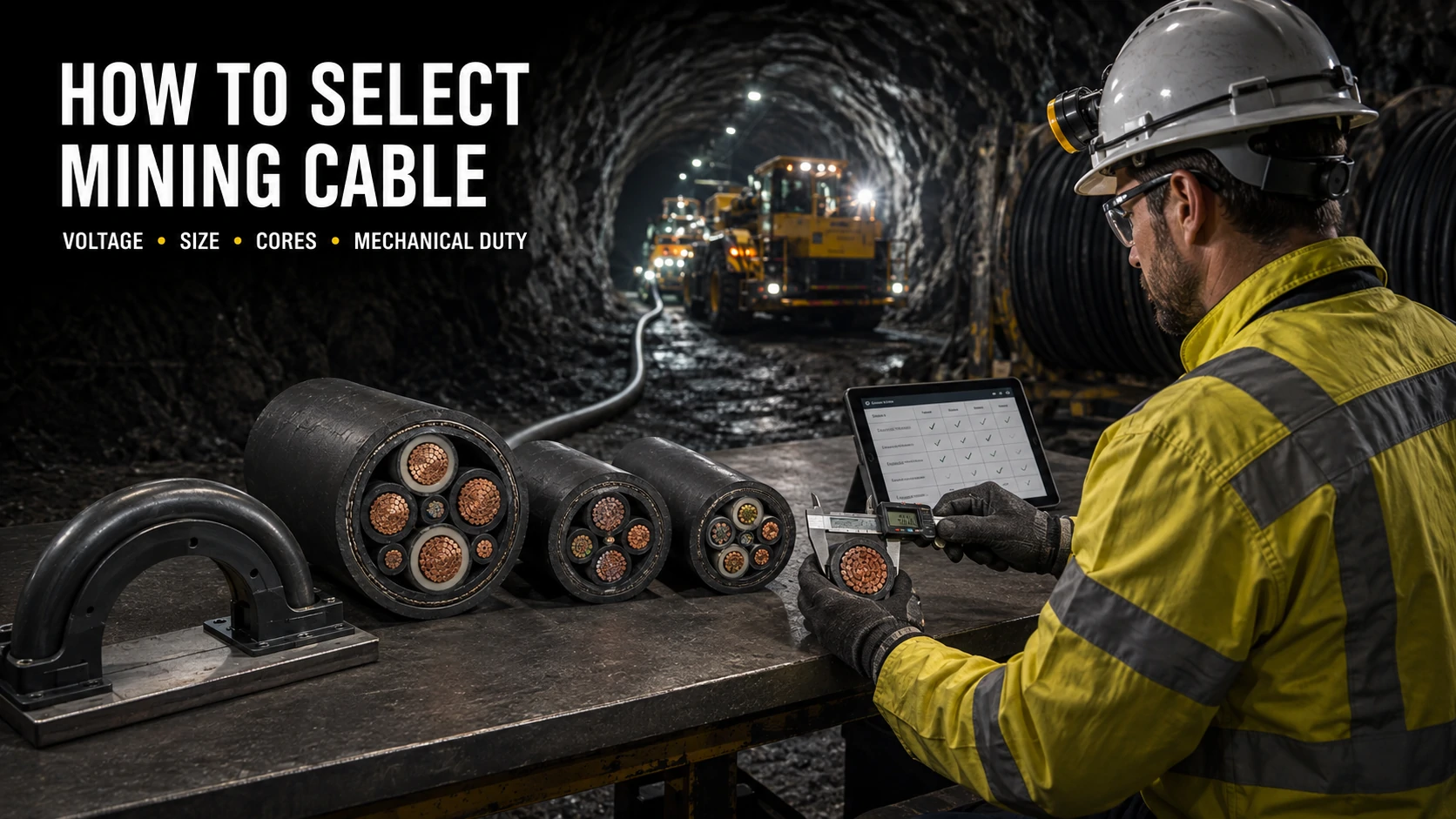
To determine how to select mining cable for a mine circuit, record the machine, network, route, movement and governing rules before choosing a type code. A cable that passes the voltage check may still fail because it overheats, drops too much voltage during motor starting, lacks the required ground-check core or cannot tolerate the bending cycle.
Mining cable selection is therefore a sequence of linked checks:
- Identify the mine jurisdiction, equipment and cable movement.
- Match the cable voltage rating to the network and earthing system.
- Calculate conductor size for ampacity, starting duty, voltage drop and fault conditions.
- Define every power, grounding, pilot, control and monitoring core.
- Check route length, bend radius, tension, torsion and cable-management equipment.
- Verify the final construction against the required standard, approval and equipment interface.
No single mining cable model is valid worldwide. ANSI/ICEA S-75-381/NEMA WC 58 covers portable and power-feeder cables for mines in North American practice. AS/NZS 1802:2018 applies to reeling and trailing cables for underground coal mining, while AS/NZS 2802:2000 covers mining and general use other than underground coal mining. The project specification must name the applicable document and edition. (Sources: ICEA portable-cable documents, AS/NZS 1802:2018, AS/NZS 2802:2000)
How Do I Choose the Right Mining Cable?
Start with Equipment, Route and Movement
Choose the cable family from its actual work cycle, not from voltage or conductor area alone. A 6 kV cable fixed beside a conveyor has a different construction duty from a 6 kV cable that winds onto a shovel reel throughout each shift.
| Equipment or route | Cable movement | Data that controls the mechanical choice |
|---|---|---|
| Fixed pump, fan or conveyor | Stationary after installation | Support spacing, moisture, impact protection and installation bends |
| Continuous miner, drill or shuttle car | Trails behind the machine | Drag distance, repeated flexing, runovers, cuts and strain relief |
| Shovel, dragline or reel-fed vehicle | Reels and unreels | Drum diameter, speed, acceleration, tension, torsion and fleet angle |
| Longwall shearer | Moves through a cable handler or chain | Chain geometry, small repeated bends, travel stroke and pilot-core fatigue |
| Mobile substation or power center | Periodically relocated | Handling method, couplers, pulling load and relocation frequency |
| Shaft, borehole or vertical rise | Suspended or restrained vertically | Cable weight, support interval, tensile member and water exposure |
The route survey should mark every reel, sheave, guide, clamp, S-bend, crossing and unprotected floor section. Record the smallest available radius and the length that moves. A drawing that only shows the two termination points hides most causes of mechanical damage.
Prysmian separates mining applications into reeling, trailing, cable-handler, pump, fixed-conveyor and tunnelling duties. Its mining literature also lists tension, torsion from guide misalignment, bending radius, travel speed and acceleration as separate design conditions. Those categories show why “flexible mining cable” is not a complete specification. (Source: Prysmian Mining & Tunnelling Cables)
Seven Inputs Required Before Selection
Seven input groups are needed before a supplier or engineer can select a construction. Missing information should remain marked “TBC”; it should not be replaced with an assumed value.
| Input | What to provide | What it determines |
|---|---|---|
| 1. Jurisdiction and mine class | Country, underground coal, other underground, surface mine, quarry or processing plant; required standard and edition | Flame tests, approvals, shielding, grounding and permitted cable types |
| 2. Equipment and circuit | Machine, motor or load, fixed/mobile status, AC or DC, phase count and frequency | Cable family, power-core arrangement and connection method |
| 3. Electrical network | Nominal and maximum voltage, earthing method, fault level, protective-device type and clearing time | Rated voltage, screens, insulation level and short-circuit withstand |
| 4. Load profile | Nameplate current, maximum operating current, start method, starting current/time, starts per hour and duty cycle | Conductor ampacity, thermal cycle and starting-voltage check |
| 5. Route | One-way length, elevation change, installation method, supports, grouping and smallest route radius | Voltage drop, remote-end fault current, derating and cable diameter limit |
| 6. Movement | Fixed, trailing, reeling, festooned or cable-chain duty; speed, acceleration, tension, torsion and cycles | Stranding, core lay, reinforcement, sheath and dynamic bend radius |
| 7. Environment and interfaces | Temperature, water, oil, chemicals, UV, abrasion, crushing, couplers, glands, reel and drum lengths | Materials, outer diameter, terminations, tests and delivery construction |
A request such as 6/10 kV, 3 × 70 mm² mining cable gives a voltage class and three phase conductors. It does not state the mine class, grounding arrangement, ground-check circuit, shields, movement, ampacity conditions, route length or bend radius.
What Voltage Rating Should a Mining Cable Have?
Understanding U0/U and System Voltage
The cable rating must cover both conductor-to-earth and conductor-to-conductor voltage under the network’s earthing arrangement. In IEC-style notation, the two figures do not describe a normal and an overload value.
| Symbol | Meaning | Selection question |
|---|---|---|
| U₀ | Rated RMS voltage between an insulated conductor and earth or an earthed metallic covering | What voltage can appear from a phase core to ground or its screen? |
| U | Rated RMS voltage between two phase conductors | What is the system’s phase-to-phase voltage? |
| Uₘ | Highest system voltage associated with the equipment voltage class | What maximum network voltage must the cable system accommodate? |
For a cable marked 6/10 (12) kV, 6 kV is U₀, 10 kV is U and 12 kV is Uₘ. A system engineer must confirm that all three values align with the network, its normal voltage variation and earth-fault behavior. Prysmian’s cable guide defines U₀ as conductor-to-earth or conductor-to-earthed-cover voltage and U as voltage between phase conductors. IEC 60502 also expresses its voltage classes with Uₘ, such as 6 kV cables associated with Uₘ = 7.2 kV. (Sources: Prysmian general cable information, IEC 60502-2:2014+A1:2024)
North American mining data sheets often state a class such as 2,000 V, 5 kV, 15 kV or 25 kV instead of putting U₀/U on the product name. Do not convert between naming systems from the printed number alone. Use the governing standard, cable construction sheet and system single-line diagram.
A higher printed voltage class is not automatic proof of suitability. Voltage rating does not confirm ampacity, flex life, shielding, ground monitoring, jacket performance, coupler compatibility or authority acceptance.
Equipment Nameplate, Network and Fault Conditions
The equipment nameplate is the starting record, but the network study completes the voltage selection. Collect the following values from approved drawings and protection studies:
- Equipment nameplate voltage and permitted operating range
- Transformer secondary voltage and tap range
- Nominal and highest operating voltage at the cable source
- Phase-to-phase and phase-to-ground voltages
- Solidly grounded, resistance-grounded, impedance-grounded or ungrounded system arrangement
- Maximum earth-fault current and ground-fault trip setting
- Maximum and minimum short-circuit current at both cable ends
- Protective-device clearing time
- Drive type, switching waveform and any transient-overvoltage study
Earthing affects the voltage imposed on insulation during a ground fault. The same nominal phase-to-phase voltage can produce different conductor-to-earth duties in a solidly grounded system and a system allowed to continue briefly with one phase grounded.
Regulation can also change the cable construction at a stated equipment voltage. Under U.S. 30 CFR §18.47, portable cable for permissible equipment rated 661–1,000 V must include grounding conductors, a ground-check conductor and grounded metallic shielding, subject to a stated reel-cable exception. Equipment rated 1,001–4,160 V requires grounding conductors, a ground-check conductor and a grounded metallic shield around each power conductor. These are U.S. requirements for the equipment covered by that rule, not universal voltage bands. (Source: 30 CFR §18.47)
The voltage check also covers terminations. Couplers, receptacles, glands, stress-control components, screens and cable repair kits must have ratings and approvals compatible with the cable and network.
How Do I Select Mining Cable Conductor Size and Ampacity?
Load Current, Duty Cycle and Starting Current
Select conductor area by passing four electrical tests: continuous or cyclic ampacity, operating voltage drop, starting performance and short-circuit protection. The largest area required by any test becomes the electrical minimum before mechanical constraints are reviewed.
Use measured current or the equipment nameplate where available. Motor kilowatts alone are insufficient because efficiency and power factor change the current. For an early three-phase estimate when Pout is shaft output:
Iest = Pout / (√3 × V × η × cos φ)
The final calculation must replace estimated efficiency, power factor and current with the motor data sheet, drive data and operating load profile.
Four conductor-size checks
| Check | Data required | Pass condition |
|---|---|---|
| Thermal ampacity | Load current, duty cycle, ambient conditions, cable construction and installation method | Conductor temperature remains within the specified limit |
| Running and starting voltage | Cable R and X, length, power factor, running current, starting current/time and upstream impedance | Equipment voltage remains within its permitted operating and starting range |
| Maximum fault withstand | Prospective fault current and clearing time | Conductors, grounds and screens survive until protection opens |
| Minimum fault operation | Remote-end fault current and protection curve | Protective device trips within the time required by the protection design |
Starting current should not be treated as continuous load current. Schneider Electric gives about 6 × rated current for 5–30 seconds as an average direct-on-line asynchronous-motor example; the actual locked-rotor current and acceleration time must come from the selected motor and load. Repeated starts, stalled cutting heads or long acceleration periods can create a much heavier thermal cycle than one normal start. (Source: Schneider Electric motor-starting parameters)
Mobile mine machines often have fluctuating loads. Record current against time through a representative cutting, hauling or drilling cycle rather than applying a guessed diversity factor. MSHA guidance for some approval evaluations compares average duty-cycle ampacity with ICEA mine-trailing-cable ampacity tables; this does not authorize a general overload factor for every mine or cable. (Source: MSHA PIB P10-20)
Published ampacity belongs to a named construction and stated test basis. One Prysmian 2 kV, 90°C, three-conductor Type G-GC table lists the following values:
| Phase-conductor size | Published ampacity |
|---|---|
| 6 AWG | 79 A |
| 4 AWG | 104 A |
| 2 AWG | 138 A |
| 1/0 AWG | 186 A |
These numbers illustrate the relationship within that product table; they are not conversion values for another mining cable, installation or jurisdiction. (Source: Prysmian 2 kV Type G-GC data sheet)
Fault duty is a separate calculation. IEC 60949 provides a method for thermally permissible short-circuit current, including a non-adiabatic correction. ICEA lists P-32-382 for insulated-cable short-circuit characteristics and P-45-482 for metallic shields and sheaths. Use the method required by the project, with the actual initial temperature, final permitted temperature and protection clearing time. (Sources: IEC 60949, ICEA cable documents)
Ambient Temperature, Grouping and Derating
An ampacity table is valid only under its stated thermal conditions. Ambient temperature, mutual heating and restricted heat dissipation can reduce the usable current below the published reference value.
Where the governing method permits multiplicative correction factors, the working form is:
Iz,corrected = Iz,reference × ktemperature × kgrouping × kinstallation × kother
The factors must come from one compatible standard or engineering calculation. Mixing a temperature factor from one system with a grouping factor and base ampacity from unrelated tables can produce an unsupported result.
Check the cable in every thermal state along its route:
- Uncoiled in free air or supported along a wall
- Grouped with other loaded cables
- Covered by mud, fines or accumulated material
- Installed in tray, conduit, duct or borehole
- Exposed to sun at a surface mine
- Submerged or routed through warm water
- Wound in several layers on a powered reel
- Passing through a gland, coupler or enclosure with a lower current rating
IEC 60287-1-1:2023 calculates steady-state ratings at a 100% load factor and leaves construction, site and agreed safety-margin parameters to the calculation. IEC 60287-2-2 addresses reduction factors for groups of equal cables in free air protected from solar radiation. Neither title turns a fixed-installation table into a dynamic-reeling rating. (Sources: IEC 60287-1-1:2023, IEC 60287-2-2:1995)
A cable wound on a drum needs the manufacturer’s reel-loading method, permitted number of energized layers and operating cycle. Heat trapped in inner layers can control conductor size even when the paid-out cable has ample ampacity.
How Many Power, Ground and Pilot Cores Are Required?
Power and Equipment Grounding Conductors
Core count follows the circuit and protection scheme. A three-phase motor normally needs three phase conductors, but that fact does not determine the number or size of grounding, ground-check, pilot, control or monitoring cores.
| Component | Normal function | Selection basis |
|---|---|---|
| Phase conductor | Carries operating and starting current | Load, ampacity, voltage drop and fault withstand |
| Neutral, when required | Carries unbalanced or single-phase load current | System architecture, harmonics and local rules |
| Equipment-grounding conductor | Bonds exposed metal and carries fault current toward the source | Fault current, clearing time, standard and cable geometry |
| Metallic phase shield | Controls the electric field and carries charging or fault current | Voltage class, earthing, protection and standard |
| Overall metallic shield | Provides the function specified by its cable design | Standard, circuit arrangement and termination method |
Do not count metallic shields as equipment-grounding conductors unless the governing design explicitly assigns and verifies that function. The grounding circuit must remain continuous through the cable, couplers, junction boxes and machine frame.
Regional rules may prescribe ground-conductor area. For U.S. underground coal-mine mobile equipment, 30 CFR §75.906 states that one or more ground conductors must have a combined cross-sectional area of at least one-half the power conductor. For underground high-voltage cables in resistance-grounded systems, §75.804 also specifies metallic shields and ground-check-conductor provisions. These values should not be transferred to a different jurisdiction without checking its standard. (Source: 30 CFR Part 75, §§75.804 and 75.906)
Several smaller grounding conductors may be placed symmetrically around the phase cores in a flexible cable. Their combined area, strand construction, fault rating and connection method must all comply; simply adding nominal areas does not verify the termination or fault-current path.
Pilot, Ground-Check, Control and Monitoring Cores
A ground-check conductor monitors the protective grounding circuit; it does not carry the normal equipment fault current and does not replace the grounding conductor. The relay scheme should de-energize the circuit if continuity is lost.
U.S. rules illustrate the distinction. 30 CFR §75.902 requires a fail-safe ground-check circuit for covered low- and medium-voltage resistance-grounded systems and requires the circuit breaker to open if the ground or pilot-check wire breaks. §75.803 states the corresponding principle for high-voltage resistance-grounded systems. (Source: 30 CFR Part 75 ground-check provisions)
The word pilot is not a universal core description. Depending on the cable standard and machine drawing, it may refer to:
- A ground-continuity check conductor
- A permissive or interlock circuit
- A control or emergency-stop circuit
- A temperature, position or condition-monitoring circuit
- A screened pair for analogue or digital signals
Specify each core by function, quantity, conductor size, insulation voltage, identification and termination pin. For a reel or cable-chain application, confirm that the pilot-core stranding and position within the cable are rated for the same flex cycle as the power assembly.
Power and communication elements may share one outer sheath only where the standard and equipment design permit it. Screened pairs, coaxial elements or optical fibers need their own mechanical and electrical compatibility review, especially at couplers and repair points.
Product codes give clues but do not replace the construction drawing. In North American naming, G-GC contains grounding and ground-check conductors, while shielded SHD-GC also uses phase shielding. A visually similar code from another national system may not have the same core arrangement.
How Do Cable Length, Voltage Drop and Bend Radius Affect Selection?
Voltage Drop over Long Cable Runs
Long cable runs can control phase-conductor area even when ampacity is adequate. Length raises running voltage drop, deepens the dip during motor starting and reduces the fault current available at the remote end.
For a balanced three-phase circuit, a common steady-state expression is:
ΔU = √3 × I × (R cos φ + X sin φ) × L
For a single-phase two-wire circuit:
ΔU = 2 × I × (R cos φ + X sin φ) × L
Use R and X in ohms per kilometre, one-way length L in kilometres, and resistance at the expected conductor temperature. Convert to percentage with 100 × ΔU / Un. Manufacturer values should replace simplified resistivity estimates for the final check. (Source: Schneider Electric voltage-drop calculation)
Run at least three cases:
- Maximum normal operating current at the lowest expected source voltage
- Motor starting current and power factor for the complete acceleration time
- Minimum phase fault or earth-fault current at the far end of the cable
The third case is a protection check rather than a voltage-quality check. An extended cable can limit fault current enough that an instantaneous element no longer trips as intended.
A published IEC-based example shows the scale of the starting problem. A 400 V, three-phase motor supplied through 50 m of 35 mm² copper cable draws 100 A at normal load and 500 A during starting. In the example, the cable contributes 5 V drop in normal service and 13.5 V during starting; after upstream drop is added, the totals are 3.75% and 6.9%. The figures are instructional, not mining-cable limits. (Source: Schneider Electric worked voltage-drop example)
Permitted voltage drop comes from the mine standard, equipment manufacturer and protection study. A general percentage copied from a building-wiring guide may not suit a continuous miner, conveyor, high-inertia pump or resistance-grounded mobile system.
Length limits can also be regulatory. MSHA guidance for certain U.S. permissible face equipment explains additional evaluation and approval paths for trailing cables over 500 ft when protection settings depart from the normal tables. That is a mine-specific protection issue, not a universal 500 ft maximum for every mining cable. (Source: MSHA PIB P11-07)
Minimum Bend Radius and Route Geometry
Minimum bend radius is a construction-specific limit, normally expressed as a multiple of overall cable diameter D. Use the larger value required for the actual condition: installation, fixed service, repeated flexing, reeling or cable-chain movement.
Rmin = k × D
If a 50 mm cable has a published dynamic factor of 10D, the minimum dynamic radius is 500 mm. Confirm whether the data sheet measures radius to the cable centreline or another reference before selecting a drum, sheave or guide.
The multiplier is not universal. Two Prysmian mining examples show the range:
| Mining cable example | Fixed bend radius | Flexible-operation bend radius | Other route limit |
|---|---|---|---|
| CORDAFLEX reeling cable | 4D | 5D | 20D minimum distance through S-type directional changes |
| TENAX-LUMEN trailing cable | 6D | 10D | Product-specific tension and torsion limits also apply |
Those figures belong to the named products. Another cable may need a larger radius because of conductor size, screens, reinforcement, temperature or movement pattern. (Sources: Prysmian CORDAFLEX data, Prysmian TENAX-LUMEN data)
Check route geometry after the actual cable diameter is known. A larger conductor can solve voltage drop but increase overall diameter enough to violate the existing reel or cable-chain radius.
The mechanical review should cover:
- Reel core, sheave and roller diameters
- Groove width and cable sidewall pressure
- Guide alignment and fleet angle
- S-bend spacing and reverse-bending frequency
- Pulling tension, suspended weight and strain relief
- Torsion per metre and machine turning pattern
- Reeling speed, acceleration and emergency stops
- Cable accumulation, crushing and runover points
- Clearances at couplers, glands and cable-handler links
A route that forces one bend below the published radius is not corrected by making the remaining route gentler. Change the route hardware, available space or cable construction before release.
Mining Cable Selection Checklist
Technical Data Required from the Buyer
A buyer should send a completed data sheet rather than a model guess. The following checklist is sufficient for an initial engineering review and quotation; the supplier may request more information after checking the standard and equipment.
| Data field | Buyer input |
|---|---|
| Destination country and mine | Country, mine name or project, underground/surface and coal/non-coal classification |
| Required compliance | Standard, edition, approval authority, flame test and mine-specific specification |
| Equipment | Machine type, manufacturer, model, motor/load and fixed or mobile duty |
| Network | AC/DC, nominal voltage, U₀/U/Uₘ if used, phases, frequency and earthing method |
| Load | Nameplate power and current, maximum measured current and duty cycle |
| Starting | DOL, star-delta, soft starter or VFD; starting current, starting time and starts per hour |
| Fault and protection | Maximum/minimum fault level, ground-fault limit, protective device and clearing time |
| Cable movement | Fixed, relocated, trailing, reeling, festooned or cable chain; travel distance and cycles |
| Route | One-way length, elevation, supports, grouping, smallest bend and exposed sections |
| Reel or handler | Drum/core dimensions, number of layers, speed, tension, guides, sheaves and fleet angle |
| Core arrangement | Power cores, neutral, grounding conductors, ground check, pilots, controls and data elements |
| Environment | Ambient range, water depth, mud, oil, chemicals, UV, abrasion, crushing and flame conditions |
| Connections | Coupler, plug, receptacle, gland, termination drawing and pin allocation |
| Delivery | Total quantity, individual working lengths, drum limits, packing and inspection documents |
The buyer can copy the following short format into an enquiry:
Country / mine classification:
Required standard and approval:
Equipment and movement duty:
System voltage / phases / frequency / earthing:
Nameplate current / starting method / starting time:
Maximum and minimum fault current / protection clearing time:
Power, ground, ground-check, pilot and control cores:
One-way cable length:
Minimum available route radius / reel or sheave data:
Temperature, water, oil, chemical and abrasion exposure:
Couplers or terminations:
Required working lengths and total quantity:
Photos of the existing jacket marking, cable reel, couplers and route can clarify the enquiry, but they do not replace the single-line diagram, load data or required standard.
Final Engineering and Compliance Verification
Release the cable only after the manufacturer’s construction sheet and project calculation pass the same verification matrix. A commercial quotation that lists voltage, cores and conductor area is not a finished engineering approval.
| Verification item | Evidence to review before order |
|---|---|
| Standard and authority | Named standard and edition, approval or acceptance number, jurisdiction confirmation |
| Cable construction | Cross-sectional drawing, materials, conductor class, screens, grounds, pilots and reinforcement |
| Voltage | U₀/U/Uₘ or regional voltage class matched to network and earthing study |
| Ampacity | Published basis or calculation, duty cycle and all applicable derating factors |
| Voltage drop | Running and starting cases using cable R/X and upstream impedance |
| Fault performance | Maximum thermal withstand and minimum fault current for protective-device operation |
| Core functions | Grounding, ground-check, control and monitoring schematic with termination pins |
| Mechanical duty | Fixed/dynamic bend radius, tension, torsion, speed, reel and cable-handler compatibility |
| Environment | Temperature range and named tests for water, oil, chemicals, UV, flame and abrasion |
| Accessories | Coupler, gland, splice/repair kit and termination compatibility |
| Production and tests | Routine test plan, requested type-test evidence, inspection documents and traceable marking |
| Logistics | Continuous working length, drum dimensions, gross weight, handling direction and packing |
Substitution needs a full recheck. A replacement with the same printed voltage and conductor area can have a different diameter, ampacity, ground arrangement, shield, bend radius or approval.
For a project enquiry, compare the completed checklist with the HUALUO Cable mining cable range and request a project-specific construction sheet. Final selection should be signed off by the mine’s qualified electrical engineer or other responsible authority under the applicable rules.