
What Is a Solar Cable? Types and Applications
What is a solar cable? It is an electrical cable designed for photovoltaic (PV) circuits, commonly used to carry DC power between solar modules and associated equipment. Its voltage rating, construction and environmental performance must suit the circuit and installation conditions.
The terms solar cable, PV cable and PV wire often overlap, but they do not always identify the same product specification. Buyers also need to distinguish PV array wiring from battery and AC wiring, and separate single-core cables from products sold as twin cable.
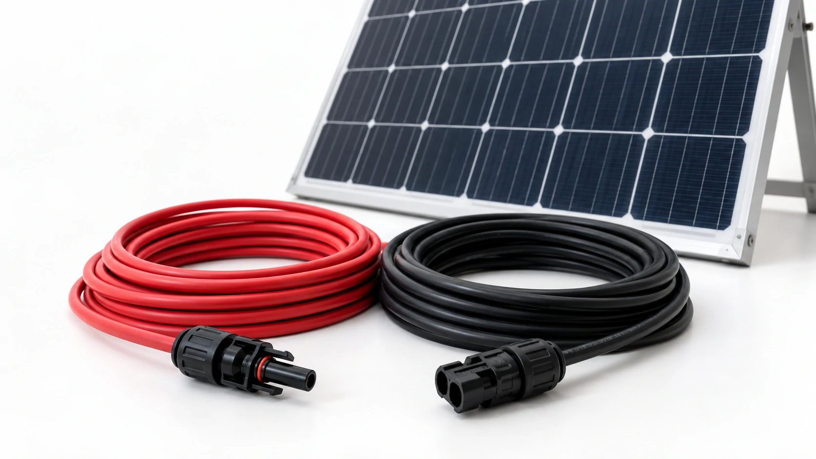
What Is a Solar Cable?
A Direct Definition of Solar Cable
A solar cable provides an insulated electrical connection within a photovoltaic system. In product catalogues and purchasing discussions, the term usually refers to cables intended for the DC side of a PV array.
These cables may operate outdoors, where sunlight, moisture and temperature changes affect their insulating and protective materials. Suitability for a particular location depends on the exact cable’s ratings and documented installation conditions.
Many solar cable designs use stranded conductors surrounded by insulation and a protective outer covering. However, conductor material, insulation composition and sheath construction vary between products.
A solar cable’s name alone does not establish its voltage rating, conductor size, permitted installation method or certification. Those details belong in the product specification.
The Role of Cable in a Photovoltaic Circuit
Solar cables carry the DC electricity generated by PV modules toward equipment that converts or regulates it. Depending on the system, that equipment may be an inverter or a solar charge controller.
Modules connected in series form a string. String wiring connects these groups to the next electrical connection point, such as a combiner box or an inverter input.
The conductor carries current, while the insulation electrically separates it from other conductors and surrounding objects. The outer covering provides the protection specified for the cable’s intended environment.
Cable resistance also causes voltage drop and power loss. The required conductor size therefore depends on current, route length, installation conditions and the permitted voltage drop. A cable can belong to the correct product category yet still be unsuitable for a particular circuit if its conductor size or ratings are inadequate.
Are Solar Cable, PV Cable and PV Wire the Same?
Common Industry Terms and Their Meanings
In purchasing discussions, the question “what is a solar cable?” often leads to two related terms: PV cable and PV wire. These names describe overlapping product categories, but they do not guarantee identical construction or approval. Their meaning depends on the market and the specification accompanying the name.
| Term | Common meaning | What buyers should confirm |
|---|---|---|
| Solar cable | A broad commercial term for cable intended for photovoltaic applications | Product designation, electrical ratings and intended circuit |
| PV cable | Photovoltaic cable, often used interchangeably with solar cable | Applicable standard, construction and installation conditions |
| PV wire | A general description in some markets and a specific product designation in others | Whether the term refers to certified Type PV wire or informal sales terminology |
The words “wire” and “cable” do not reliably identify core count or conductor construction. A product sold as PV wire may contain a stranded conductor, while a product sold as solar cable may contain only one core.
A useful purchase specification combines the product designation with conductor size, voltage rating, applicable standard and construction. Hualuo Cable’s solar cable product range includes H1Z2Z2-K and PV1-F, giving buyers specific model references to discuss when preparing an enquiry.
A description such as “solar cable, 6 mm²” still leaves the required standard, voltage rating and construction unresolved.
Why PV Wire Can Have a Specific Meaning in North America
In the United States, “PV Wire” can identify a product category evaluated under UL 4703. It is more specific than a general description of wire used in a solar installation.
The published scope of UL 4703 covers single-conductor, insulated, jacketed, sunlight-resistant photovoltaic wire for interconnection wiring in PV systems. See the UL 4703 product scope.
A cable described as “solar cable” in an international quotation should therefore not automatically be treated as UL-listed PV Wire. Buyers should check the product marking, certification record and coverage of the exact model offered.
North American markets also have different product designations. UL’s published material distinguishes Type PV wire evaluated under UL 4703 in the United States and Mexico from Type RPVU cables evaluated under CSA C22.2 No. 271 in Canada. See UL’s photovoltaic cable designation notes.
For procurement, identify the destination market and required approval before comparing products. Similar appearance and conductor size do not establish equivalent acceptance.
Where Are Solar Cables Used in a PV System?
Module Leads, String Wiring and Array Connections
Solar cables commonly serve module connections, string extensions and specified DC connections within a PV array. Their exact application points depend on the system architecture.
| Application point | Cable function | Main specification consideration |
|---|---|---|
| Module leads | Connect a module’s junction box to its external connection points | Module assembly requirements and connector compatibility |
| String wiring and extensions | Connect modules in series and extend string connections | Circuit voltage, current, routing and outdoor exposure |
| String-to-combiner connections | Carry individual string outputs to a combining point | String circuit ratings and termination requirements |
| Array-to-inverter DC connections | Carry DC power toward inverter inputs, directly or through intermediate equipment | Combined current where applicable, route length and installation method |
Not every installation uses a separate combiner box. Some string inverters accept multiple strings directly. Systems with microinverters convert DC to AC near the modules, so much of their downstream wiring serves an AC circuit.
Module leads and field-installed extensions also require compatible connection interfaces. Conductor size alone does not establish connector compatibility: cable outside diameter and conductor construction must fall within the connector’s specified range.
The term “solar cable” does not automatically establish suitability for direct burial, continuous water exposure or every cable-management arrangement. Confirm these conditions in the documentation for the exact product.
Separating PV Array Wiring from Battery and AC Circuits
PV array wiring, battery wiring and AC wiring perform different duties, even when they belong to the same installation. Each circuit needs its own cable specification.
| Circuit | Electrical role | Why it requires separate consideration |
|---|---|---|
| PV array DC circuit | Carries electricity generated by the modules | Array voltage, outdoor exposure and PV wiring requirements |
| Battery DC circuit | Connects energy storage to charging or power-conversion equipment | Charge and discharge current, fault conditions and terminal requirements |
| Inverter AC circuit | Carries converted AC power to distribution equipment or loads | AC wiring requirements, conductor arrangement and installation method |
Battery circuits can carry substantial current, particularly in lower-voltage storage systems. A conductor selected for a PV string may be too small for a battery connection.
Likewise, an outdoor-rated PV cable does not automatically satisfy the requirements for an inverter’s AC output. Its suitability depends on the electrical duty and permitted wiring methods for that circuit.
When requesting a quotation, name the connection explicitly. “PV string to inverter DC input” describes the application more clearly than “cable for a solar system.”
This distinction helps buyers avoid specifying one cable type for several circuits with different requirements.
What Is the Difference Between Single-Core and Twin Solar Cable?
Separate Single-Core Cables and Paired Cable Designs
A single-core solar cable contains one insulated conductor. “Twin solar cable” generally describes two conductors supplied together, but the term does not fully define their physical arrangement.
A PV DC circuit commonly uses separate positive and negative conductors. These can be supplied as individual single-core cables and routed together according to the installation design.
Products marketed as twin solar cable may consist of:
- Two individually insulated and jacketed cables joined side by side.
- Two insulated cores enclosed within a common outer sheath.
- Two separate single-core cables supplied as a matched pair.
These arrangements differ in dimensions, handling and termination. Their certification coverage also needs to match the product being supplied.
| Construction | Physical arrangement | What to check |
|---|---|---|
| Separate single-core cables | Two independent cables used for the two polarities | Identification, routing and individual cable ratings |
| Joined pair | Two cables physically joined side by side | Separation method, dimensions and approval coverage |
| Two-core sheathed cable | Two insulated cores inside one common sheath | Complete cable construction and termination suitability |
| Matched pair | Two separate cables packaged or sold together | Whether the quoted quantity includes both lengths |
A joined format may help keep conductors together during installation. Separate single-core cables allow independent handling at connection points. The appropriate choice depends on the route, equipment interfaces and accepted cable construction.
The word “twin” should therefore be supported by a construction drawing or a clear datasheet description before an order is placed.
How to Read Core Count and Construction Descriptions
Core count identifies the number of conductors, while conductor cross-sectional area identifies the size of each conductor. Neither value describes the complete cable.
| Description | Usual interpretation | What it does not establish |
|---|---|---|
| 1 × 4 mm² | One core with a conductor cross-sectional area of 4 mm² | Overall diameter, voltage rating or certification |
| 1 × 6 mm² | One core with a conductor cross-sectional area of 6 mm² | Conductor material or insulation composition |
| 2 × 4 mm² | Two cores, each with a 4 mm² conductor | Whether they share a sheath or form a joined pair |
| Twin 6 mm² | Usually two conductors, each 6 mm², supplied together | Exact physical arrangement or approval scope |
| Two lengths of 1 × 6 mm² | Two separate single-core cables | Whether the stated order length is per cable or combined |
For example, 2 × 4 mm² means two conductors, each with a nominal cross-sectional area of 4 mm². It does not mean that each conductor is 8 mm². The figure 4 mm² describes an area, not a diameter of 4 mm.
A clear enquiry should identify both construction and quantity:
Two separate single-core cables, each 1 × 6 mm², one red and one black, 500 metres per colour.
This description resolves core arrangement and order length. The purchase specification should additionally identify the required voltage rating, conductor material, certification and installation conditions.
For bulk or project requirements, request a solar cable quotation with your voltage, conductor size, core count and total metres. Include the destination market and required standard so the proposed product can be checked against your specification.