
Trailing vs Reeling Mining Cable: Key Differences and Selection
- Trailing vs Reeling Mining Cable: Key Differences and Selection
- What Is a Trailing Cable?
- What Is the Difference Between Trailing and Reeling Cable?
- What Is the Difference Between Trailing and Feeder Cable?
- Can Trailing and Reeling Cables Be Used Interchangeably?
- Trailing, Reeling and Feeder Cable Selection Matrix
- Trailing Cable vs Reeling Cable: Frequently Asked Questions
The main distinction in trailing cable vs reeling cable selection is movement: trailing cables follow mobile equipment, while reeling cables undergo repeated winding and unwinding on an operating drum. Feeder describes a supply function; its permitted movement must be checked separately. [Source: WorkSafe WA, Trailing and reeling cables]
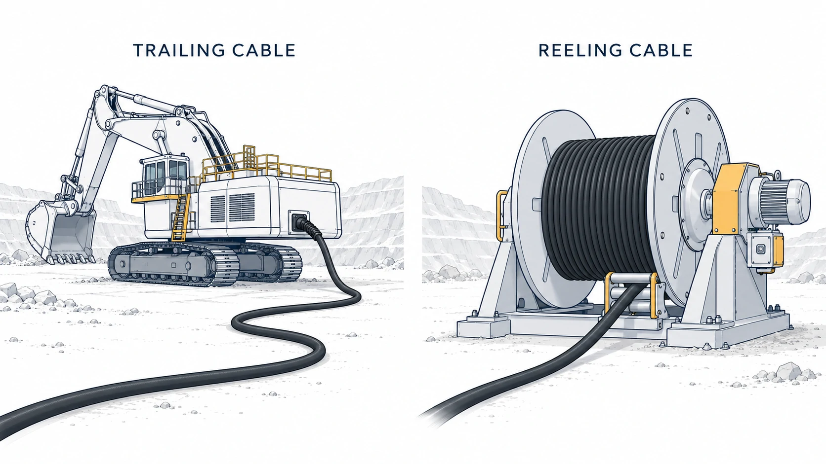
For trailing cable vs reeling cable quotations, we recommend comparing the complete cable route and handling cycle before comparing prices. A cable that fits the electrical specification can still exceed its mechanical limits at a guide roller, machine entry or drum.
What Is a Trailing Cable?
A trailing cable supplies mobile mining equipment while accommodating movement along its working route. In a trailing cable vs reeling cable comparison, the trailing application normally involves a loose or managed cable length that follows the machine.
How a Trailing Cable Moves
A trailing cable bends and changes position as the connected machine advances, reverses or relocates. Sections may slide across the ground, pass through handling equipment or remain stationary between moves.
For trailing cable vs reeling cable selection, record how the cable actually travels:
- Ground contact: broken rock, compacted soil or concrete.
- Pulling conditions: normal drag, slopes and possible snag points.
- Direction changes: tight corners, machine entries and guide locations.
- Movement frequency: occasional relocation or repeated movement throughout a shift.
A cable supplied on a wooden shipping drum does not acquire an operating reeling rating. Transport packaging says nothing about repeated winding performance.
Typical Mining Equipment Applications
Trailing applications include supplies to electric shovels, draglines and continuous miners; equipment with an active cable reel needs a separate reeling assessment. The machine name alone cannot settle a trailing cable vs reeling cable decision.
Prysmian separates excavator trailing applications from reeling applications for loaders, scoops and drills. This distinction is useful when a mine operates similar machines with different cable-handling arrangements. [Source: Prysmian, Cable solutions for mining]
Consider an open-pit excavator that periodically advances across a bench. The purchasing specification should describe the ground-contact route and relocation method, including where the cable could become trapped during movement.
What Is the Difference Between Trailing and Reeling Cable?
Trailing duty emphasizes movement along the route; reeling duty adds repeated bending around a drum under the handling system’s operating tension. A trailing cable vs reeling cable assessment must also account for any ground contact shared by both applications.
Dragging and Abrasion vs Drum Winding and Torsion
Dragging loads the sheath through surface contact, while drum winding repeatedly bends the cable and places adjacent turns under contact pressure. Torsion depends on cable guidance and machine movement; ordinary drum rotation does not automatically mean axial twisting.
| Mechanical condition | Trailing application | Reeling application |
|---|---|---|
| Abrasion | Sliding over the working surface | Contact with ground, guides and drum surfaces |
| Bending | Route changes and machine movement | Repeated drum and guide passage |
| Tension | Drag resistance and handling loads | Controlled take-up tension plus route loads |
| Torsion | Possible during turns or poor handling | Possible with misalignment or changes in guidance plane |
| Compression | Trapping or vehicle contact | Winding pressure, especially with multiple layers |
This table is an engineering comparison of operating loads, not a universal construction specification. For trailing cable vs reeling cable procurement, the supplier must assess the loads that occur together.
Nexans documents anti-torsion braids in certain mining reeling constructions to control corkscrewing. That feature addresses a defined duty; it does not justify unrestricted twisting. [Source: Nexans, POWERMINE mining solutions]
Differences in Conductor, Reinforcement and Sheath Design
The construction difference in trailing cable vs reeling cable selection involves the complete conductor assembly and reinforcement; conductor flexibility alone is insufficient. Neither category has one mandatory sheath material or reinforcement arrangement.
| Component | What to compare |
|---|---|
| Conductors | Strand construction and evidence for the intended bending duty |
| Core assembly | Support of power, earth and pilot cores during movement |
| Reinforcement | Specified tensile function and resistance to twisting |
| Sheath | Abrasion performance, tear resistance and environmental compatibility |
| Finished cable | Outside diameter, mass and permitted working loads |
IEC 60228 specifies conductor dimensions and resistance requirements. An IEC 60228 conductor designation does not establish the finished cable’s reeling endurance. [Source: IEC 60228:2023]
A published construction example makes the trailing cable vs reeling cable distinction measurable. Nexans lists the following for its BUFLEX X’Prem reeling cable:
| Published parameter | Catalogue value |
|---|---|
| Rated voltage | 0.6/1 kV |
| Fixed bending radius | 6 × cable diameter |
| Mobile bending radius | 8 × cable diameter |
| S-shaped deflection radius | 20 × cable diameter |
| Reeling speed | Up to 150 m/min |
| Maximum conductor temperature in service | 90°C |
These are product-specific catalogue values, not mining-wide limits or HUALUO product claims. Obtain the current datasheet and application confirmation before using them in a purchase specification. [Source: Nexans, Industrial catalogue, BUFLEX X’Prem, printed page 26]
What Is the Difference Between Trailing and Feeder Cable?
Trailing describes movement, while feeder describes the cable’s role in supplying equipment or a distribution point. A feeder may be fixed, relocatable or designed for movement, so the terms are not mutually exclusive.
Mobile Duty vs Fixed or Semi-Fixed Installation
A fixed or semi-fixed feeder normally stays in position during operation; the trailing cable vs reeling cable comparison concerns supplies designed for movement. For this article, semi-fixed means periodically relocated under an approved procedure rather than continuously moved in service.
Prysmian also uses feeder terminology for flexible cables supplying coal cutters and other equipment. This demonstrates why the word “feeder” cannot establish mechanical suitability. [Source: Prysmian, Mining cable applications]
Add the operating arrangement to every feeder description:
- Fixed feeder: installed on a defined, supported route.
- Relocatable feeder: moved between operating positions under a specified handling procedure.
- Mobile feeder: explicitly qualified for its trailing, reeling or other movement duty.
A trailing cable vs reeling cable review remains necessary when a purchasing document calls both alternatives “machine feeder cable.”
Flexibility, Protection and Installation Requirements
Installation protection must match the actual route, even when the cable has a thick sheath or flexible conductors. Flexibility does not establish resistance to vehicle crushing, unsupported suspension or repeated powered reeling.
For installation review, specify:
- Supports and clamps: cable-compatible dimensions and loading.
- Bends and entries: the radius required for the actual operating condition.
- Traffic crossings: an engineered protection or route-separation arrangement.
- Terminations: compatible glands, couplers and strain relief.
- Exposure: water immersion, oil contact and operating temperature where applicable.
WorkSafe WA calls for trailing and reeling cables to be located, supported and protected to reduce damage to cables and connecting devices. These installation measures remain necessary after cable selection. [Source: WorkSafe WA, Installation and protection guidance]
Can Trailing and Reeling Cables Be Used Interchangeably?
A trailing cable vs reeling cable substitution is acceptable only when the exact cable is documented as suitable for both duties under the proposed conditions. Some constructions cover both applications; a general product label is insufficient evidence.
For trailing cable vs reeling cable substitution, we recommend recording the accepted operating limits alongside the replacement part number.
Why Equal Voltage Does Not Mean Equal Mechanical Duty
Equal voltage ratings establish neither equal bending capability nor equal permissible tension. Two electrically suitable cables may require different drum geometry or cable-handling settings.
Check these items independently during trailing cable vs reeling cable evaluation:
- Electrical: voltage designation, current capacity and fault withstand.
- Mechanical: moving bend radius, working tension and reeling speed.
- Interfaces: outside diameter, mass and termination compatibility.
- Protection: earth, pilot and screening arrangements.
An illustrative geometry check shows the consequence. Assume a candidate cable has a 40 mm outside diameter and its manufacturer specifies a 12D moving bend radius:
| Calculation | Result |
|---|---|
| Required moving bend radius | 12 × 40 = 480 mm |
| Bend diameter at the same reference line | 2 × 480 = 960 mm |
This is a hypothetical calculation, not a recommended cable rating. The manufacturer must define the radius reference and corresponding drum-barrel requirement; radius and diameter must not be confused.
Cases Requiring Manufacturer or Engineer Confirmation
Obtain application confirmation whenever operating conditions fall outside the documented limits or replacement changes the cable-handling geometry.
For a trailing cable vs reeling cable substitution, flag:
- A smaller drum or additional guide rollers.
- Multiple winding layers or reverse bends.
- Higher speed, acceleration or braking loads.
- Vertical travel or unsupported hanging lengths.
- Changed water exposure or low-temperature movement.
- Different cable mass, couplers or repaired sections entering the drum.
Current capacity also needs review when energized cable remains wound. Published reeling-cable ratings can specify winding conditions, including a single layer at 30°C ambient; a rating for that arrangement cannot be transferred directly to a different winding arrangement. [Source: Prysmian, Crane cables catalogue]
Trailing, Reeling and Feeder Cable Selection Matrix
Select the operating duty first, then verify the candidate construction against its electrical and mechanical limits. Use this trailing cable vs reeling cable matrix as an initial screening tool.
| Site arrangement | Duty to specify | Main confirmation needed |
|---|---|---|
| Cable follows equipment across a bench | Trailing | Ground contact, pulling load and route bends |
| Cable repeatedly enters an operating drum | Reeling | Drum geometry, tension and winding pattern |
| Reeled cable also slides over rock | Reeling plus trailing exposure | Combined bending and abrasion duty |
| Supply remains supported along a gallery | Fixed feeder | Installation method and current capacity |
| Supply is relocated between work stages | Relocatable feeder | Handling limits and relocation procedure |
| Cable runs in a chain or festoon | Dedicated chain or festoon duty | Suitability for that handling system |
Movement and Mechanical Stress Checklist
A usable checklist describes the full working cycle, including the most demanding part of the route. Average travel speed alone leaves peak loading unresolved.
Collect these measurements for trailing cable vs reeling cable selection:
- Travel: working distance in metres and cycles per shift.
- Motion: maximum speed in m/min and acceleration in m/s².
- Geometry: drum-barrel diameter, guide dimensions and reverse bends.
- Loading: continuous and peak cable tension in N or kN.
- Winding: layer count and cable length remaining wound during operation.
- Environment: minimum moving temperature, ground condition and water exposure.
We recommend attaching a route sketch with dimensioned guides. It lets the supplier check where cable motion changes direction instead of assuming a straight pull.
Information to Include in an RFQ
An RFQ should combine the electrical specification with the machine’s cable-handling data. Requests based only on voltage, conductor size and length cannot resolve trailing cable vs reeling cable suitability.
| RFQ field | Information to provide |
|---|---|
| Equipment | Manufacturer, model and working task |
| Supply | System voltage, frequency and earthing arrangement |
| Load | Operating current, starting duty and fault data |
| Cores | Power, earth, pilot, control and communication requirements |
| Length | Installed length, travel distance and spare allowance |
| Movement | Trailing, reeling, fixed or combined duty |
| Handling | Drum and guide dimensions, speed, tension and winding layers |
| Environment | Temperature, ground contact, water and chemicals |
| Compliance | Destination market, mine type and required documents |
| Delivery | Length per drum, terminations and required delivery date |
Ask the supplier to identify the proposed cable code, applicable limits and any unresolved assumptions. This makes competing quotations easier to compare without treating an incomplete specification as an accepted design.