
Mining Cable Inspection, Repair and Replacement Guide
Mining cable inspection should check the cable’s physical condition, electrical integrity and exposure to damage along its route. A cable with exposed conductors, severe crushing, a heating splice or a suspected grounding fault should be taken out of service for assessment. Whether it can return depends on the damage, permitted repair methods and verification results.
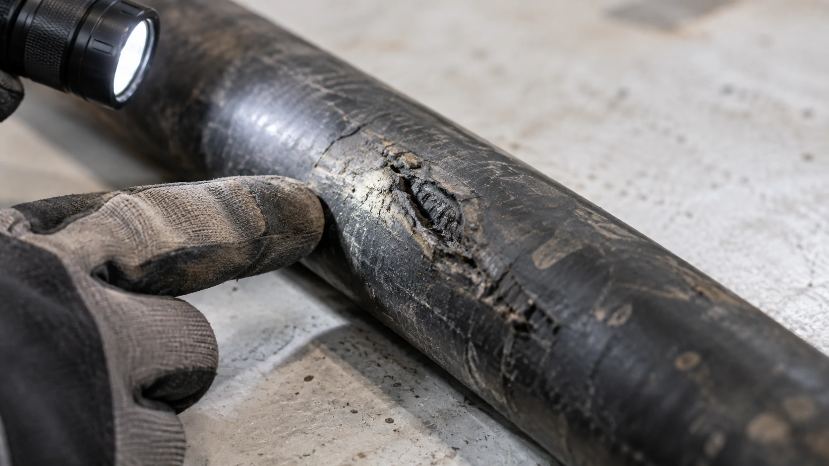
For mine maintenance teams, the immediate decision is whether continued operation is safe. Replacement comes after the condition assessment: some localized defects may be repairable, while widespread deterioration or an unsuitable cable construction may require a new cable.
Hands-on examination, testing and repair require qualified personnel working under the mine’s electrical isolation procedure. The guidance below supports maintenance planning; the applicable mining rules, cable documentation and authorized site procedures govern the actual work.
How Often Should Mining Cables Be Inspected?
Mining cable inspection frequency should reflect movement, exposure and failure history, subject to the applicable regulatory requirements. Mobile cables exposed to dragging, drum winding or vehicle traffic need closer attention than protected fixed cables. A damaging event requires assessment before further use, regardless of the scheduled inspection date.
Inspection Frequency by Movement and Site Risk
Build the inspection schedule around how each cable is used. A trailing cable can encounter a new pinch point every time a machine changes position. A reeling cable repeatedly bends at the drum and guides. A fixed feeder may remain mechanically stable but still suffer from falling material, water exposure or damaged supports.
The following is a planning framework, not a universal statutory timetable.
| Cable duty or event | Inspection approach | Areas needing attention |
|---|---|---|
| Trailing cable on mobile equipment | Include a visual check before use or at the start of each shift; reassess after relocation or suspected damage | Ground contact areas, sharp edges, machine entry and existing repairs |
| Cable repeatedly wound onto a drum | Include pre-use checks and scheduled examination based on operating duty | Drum entry, guides, crossover points, flattened areas and splice transitions |
| Protected fixed cable | Set documented inspection and test intervals from site risk and applicable requirements | Supports, terminations, moisture exposure and disturbed sections |
| Run-over, severe snag, impact or abnormal trip | Stop affected operation and arrange assessment before reuse | The affected section, adjacent cable and associated connections |
| Repaired or replaced cable | Complete the required inspection and testing before release | Repair zone, conductor identification, protective circuits and terminations |
Record which sections were actually examined. A visible length beside the machine does not establish the condition of cable hidden under debris, inside a guide or on the inner layers of a drum.
Daily Visual Checks and Periodic Electrical Tests
Daily visual checks identify accessible damage and route hazards. Electrical tests assess conditions that appearance alone cannot establish. A complete mining cable inspection program needs both, with the test scope chosen for the cable and installation.
Visual checks should cover the sheath, accessible connectors, strain relief, supports and previous repair areas. Look for fresh abrasion, open cuts, flattening, jacket movement, loose components and contamination. Any examination that requires touching, moving or opening components must follow the site’s isolation requirements.
Depending on the cable design and repair procedure, qualified personnel may need to verify conductor continuity, protective grounding continuity, insulation resistance and the ground-check circuit where fitted. Specialized tests, including proof testing or tests for partial conductor breaks, belong within the applicable cable-testing procedure. Australia’s UEEHA0036 competency covers testing reeling, trailing and flexible cables used in coal mining. Australian Government: UEEHA0036
Specify test voltage, duration, connections and acceptance criteria in the approved procedure. A single resistance threshold cannot cover every cable length, insulation system and voltage class. Keep test conditions with the results so that later readings can be compared meaningfully.
As a jurisdiction-specific example, the 2025 codified text of US 30 CFR 56.12028 requires grounding-system continuity and resistance tests after installation, repair or modification, followed by annual testing. This provision applies to surface metal and nonmetal mines; it does not establish an annual-only inspection schedule for all mining cables. 30 CFR 56.12028, 2025 edition
What Damage Means a Mining Cable Must Be Removed from Service?
Remove a mining cable from service when observed or suspected damage could compromise insulation, grounding or mechanical integrity. Keep the affected circuit isolated until the defect has been assessed and the required corrective work and verification are complete.
Cuts, Crushing, Exposed Conductors and Deformation
Exposed conductors and cuts reaching internal cable components require withdrawal from service. Severe crushing, a sharp permanent kink or localized swelling also warrants isolation because internal damage may extend beyond what is visible at the surface.
| Finding during inspection | Initial action | What the assessment must establish |
|---|---|---|
| Light surface scuffing with no apparent penetration or deformation | Record and evaluate against site acceptance criteria | Whether protective sheath thickness and condition remain acceptable |
| Open sheath cut or visible internal layer | Remove from service | Damage depth, contamination and whether a permitted repair can restore the construction |
| Exposed or broken conductor | Remove from service | Extent of conductor and insulation damage; repair eligibility |
| Severe flattening after a vehicle crossing | Remove from service | Possible strand, insulation and screen damage beyond the impact mark |
| Permanent kink, bulge or displaced jacket | Remove from service | Internal displacement and suitability for further bending or reeling |
| Split, loose or distorted previous repair | Remove from service | Integrity of the repair and the adjacent cable |
These are triage decisions, not repair acceptance criteria. A shallow mark does not automatically require scrapping the cable, but uncertainty about damage depth is a reason to hold it for qualified assessment.
Photographs help locate and document a defect. They cannot confirm insulation integrity or show how far conductor damage extends beneath the sheath.
Heating, Sparking and Grounding Faults
Sparking, smoke, melting or abnormal localized heating requires prompt shutdown through the site’s safe operating procedure. Keep clear of the affected cable and connections. Do not handle them to check temperature.
A hot splice or termination may indicate a poor connection or damaged strands. Heating over a longer length may involve loading, cooling conditions or the amount of cable remaining wound on a reel. The investigation should cover the circuit and installation as well as the visible hot spot.
A ground-fault trip or failed ground-check circuit also requires investigation. The fault may be in the cable, coupler, termination or connected equipment. Repeatedly resetting protection, or bypassing the monitoring circuit, does not resolve the cause.
For US underground coal mines, the 2025 text of 30 CFR 75.603 specifically prohibits use of trailing or hand cables with exposed wires or splices that heat or spark under load. 30 CFR 75.603, 2025 edition
Can a Mining Trailing Cable Be Spliced or Repaired?
A mining trailing cable may be repairable when the applicable rules permit the work and a suitable repair system can restore the required performance. The decision depends on the damaged layers, cable construction, voltage and mechanical duty. A sheath repair and a splice joining severed conductors require different assessments.
Temporary vs Permanent Splices
A temporary splice is subject to the limits of the applicable mining rules. It is not a general permission to continue operating with an improvised joint. Before authorizing one, establish whether it is allowed, where it may be positioned and how long the cable may remain in use.
For example, the 2025 text of US 30 CFR 75.603 allows one temporary splice in a trailing cable for the next 24 hours. It restricts placement within 25 feet of the machine, with an exception for cable reel equipment. These are provisions for US underground coal mines, not global repair limits. 30 CFR 75.603, 2025 edition
A permanent splice must meet the applicable requirements for continued service. Its dimensions and flexibility must also suit the cable’s actual movement. A repair that cannot pass through the installed guides or tolerate the required drum winding is unsuitable for that application.
Before work begins, identify the cable, the repair system’s scope and the personnel authorized to perform it. If a compliant repair cannot be completed and verified, keep the cable out of service and arrange replacement.
Mechanical Strength, Sealing and Flame Performance
A repair must restore the functions of every affected layer. Joining the phase conductors and covering the outside leaves unanswered questions about insulation, screens, grounding, sealing and repeated bending.
The repair assessment should address:
- Electrical connections: suitability for conductor material, size, stranding and current duty.
- Insulation and screens: restoration appropriate to the cable’s voltage and construction, including electric-field control where required.
- Protective circuits: correct continuity and identification of grounding and any ground-check conductors.
- Mechanical behavior: adequate strength and flexibility, with a transition suitable for the intended movement.
- Sealing and jacket performance: compatibility with the original materials, moisture exclusion and required flame performance.
The 2025 text of US 30 CFR 75.604 requires permanent trailing-cable splices to provide strength, conductivity, flexibility, insulation, moisture sealing and flame-resistant bonding. It also requires splice kits accepted or approved by MSHA as flame resistant. 30 CFR 75.604, 2025 edition
A kit’s flame approval does not establish compatibility with every cable voltage, diameter or duty. Check the kit documentation and complete the prescribed post-repair tests. The release record should identify the repair, results and person authorizing return to service.
How Long Does a Mining Cable Last?
There is no defensible service-life figure for every mining cable. Replacement decisions should use condition, operating exposure and maintenance history alongside any manufacturer or site retirement limits. Calendar age alone cannot establish fitness for service.
Why There Is No Universal Service-Life Number
A cable feeding fixed equipment experiences a different mechanical workload from one dragged over rock or wound onto a drum throughout a shift. Even identical cables can deteriorate at different rates when their routes, loading or handling differ.
Repeated bending can fatigue conductor strands. Abrasion removes protective jacket material. Excess heat and incompatible chemicals can alter insulation or sheath properties. A single severe run-over incident can make a relatively new cable unfit for service.
A laboratory flex-cycle result applies to the stated test conditions. Translating it into years at a mine requires evidence about the actual bend radius, tension, movement frequency and environment. A product warranty likewise does not establish the cable’s remaining safe operating life.
Use mining cable inspection records to track changes: recurring defects at a guide, increasing repair frequency or deteriorating test results should trigger a review of both the cable and its installation.
Repair-or-Replace Decision Factors
Findings from mining cable inspection, together with electrical test results and repair history, should guide the repair-or-replace decision. Repair is worth considering when damage is localized, the surrounding cable remains sound and a permitted method can restore suitability for the intended duty. Replace the cable when these conditions cannot be demonstrated.
| Decision factor | Repair may be suitable when… | Replacement is favored when… |
|---|---|---|
| Extent of damage | The affected section is clearly bounded | Deterioration or suspected damage extends through substantial lengths |
| Material condition | Adjacent sheath and insulation remain serviceable | Widespread cracking, embrittlement or chemical damage is present |
| Repair method | A compatible, permitted system is available | The required construction or performance cannot be restored |
| Verification | Required inspection and tests meet acceptance criteria | Results fail or a recurring fault remains unresolved |
| Mechanical duty | The repaired cable suits the drum, guides and movement | The splice would create an unsuitable bending or handling condition |
| Repair history | An isolated defect has a correctable cause | Failures recur or applicable splice restrictions would be exceeded |
| Remaining length | Removing the damaged portion leaves adequate working length | Shortening would place excess strain on the cable or connections |
Compare total outage cost only after technical acceptability has been established. Include removal, repair, testing and reinstallation. For replacement procurement, retain the original specification and record what caused the failure; buying the same cable will not correct a damaging route or an unsuitable reeling arrangement.
How to Extend Mining Cable Service Life?
Service life improves when the causes recorded during mining cable inspection lead to changes in routing, handling or equipment setup. Repeated abrasion at one location should prompt correction of that contact point as well as assessment of the damaged cable.
Routing, Clamping and Mechanical Protection
Plan the cable path around the machine’s full operating movement. Keep it away from wheel paths, tracks, sharp edges and locations where it can become trapped between moving structures. Where crossings are unavoidable, use engineered protection suitable for the traffic and installation.
Allow enough managed length for travel without pulling terminations. Excess loose cable also needs protection: uncontrolled loops can snag or be driven over.
Clamps and supports should suit the cable diameter and construction. They must restrain the cable without crushing its sheath or transferring damaging loads into electrical connections. In the US surface metal and nonmetal mine rules, 30 CFR 56.12038 addresses attachment to machines, while 56.12039 addresses protection of surplus trailing cable. 30 CFR 56.12038–12039, 2025 edition
Use the manufacturer’s specified bend radius for the actual duty. A limit for a stationary installed bend should not be assumed suitable for repeated movement. Check the repaired section against the same operating requirements.
Reeling, Handling, Storage and Maintenance Records
Match the cable to the reel system’s operating requirements, including drum geometry, winding arrangement, speed and tension. Check guides and rollers for wear or seizure, and investigate uneven winding before it produces recurring cable damage. Follow the specified loading limits when part of the energized cable remains on the drum.
During handling and storage, protect cable ends from water ingress, support reels correctly and keep lifting equipment off the cable surface. Inspect the reel before movement and follow the cable manufacturer’s handling-temperature limits. Southwire’s handling and storage guidance addresses end sealing, drainage, reel orientation and protection from lifting damage. Southwire: Wire & Cable Handling and Storage Guidelines
Give each cable an asset ID and keep its specification, installed length, equipment assignment and service date together. Inspection records should show the examined area, defect location, photographs where useful, test conditions and results, repair history and release status.
Record the cause of each defect and the corrective action. If successive repairs occur at the same guide, the maintenance record should lead to a guide or routing change before another cable is damaged.